I have published two blog posts about the CAN bus protocol. The first post discusses the basics of the CAN bus protocol, while the second delves into practical implementation on the STM32 Blue Pill in loopback mode. If you are a beginner to the CAN protocol and have not yet read the previous posts, I highly recommend reviewing them before starting this tutorial, as it builds upon the content covered in those earlier articles.
In this post, we will examine how to operate the CAN bus in normal mode. This mode is the preferred option for most real-time applications involving CAN implementation. It is quite similar to what we encountered in loopback mode, with the main differences being certain hardware connections and register configurations. As always, we will explore this topic in detail through a hands-on approach.
Hardware Setup
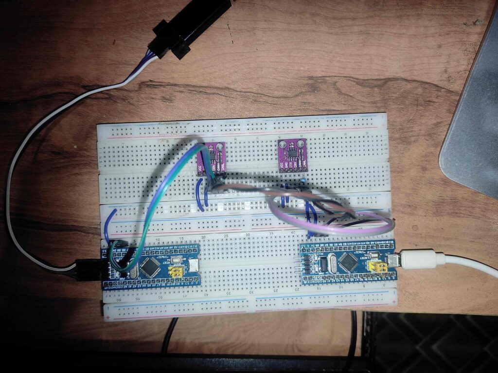
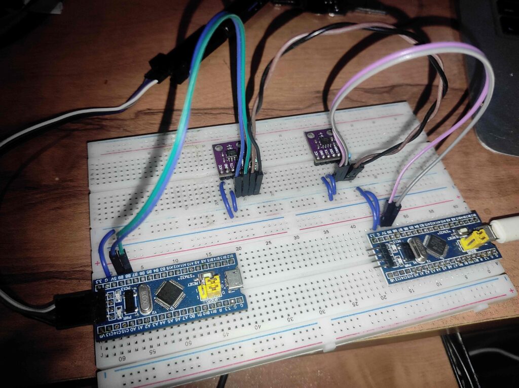
For normal mode CAN communication using two STM32 Blue Pill boards with remapped pins, connect PB9 (TX) to CTX on the MCP2551 module and PB8 (RX) to CRX. Power both the STM32 and MCP2551 with the same voltage level, either 3.3V or 5V, and connect their grounds together. Link the CANH lines of both transceivers and do the same for CANL. Since you don’t have 120Ω resistors, place 100Ω termination resistors between CANH and CANL at both ends of the bus. This setup should allow proper CAN communication between the two Blue Pill boards.
Here are some captures of my setup.
Hands-on
Establish CAN communication between two STM32 Blue Pill boards. The objective is for the first Blue Pill to send the letters ‘A’ and ‘B’ alternately, while the second Blue Pill will respond by controlling an LED. Specifically, the LED on the second Blue Pill will illuminate when it receives the letter ‘A’ and turn off when it receives the letter ‘B’.
Steps to be followed
We can follow the same steps as we followed in loopback mode. Here we are using the re-mapped CAN pins (RM0008 – Section 9.3.3) instead of the default. You can try the default pin by avoiding the extra step I have mentioned in the next section.
Common setup for both CAN Transmitter and Receiver
Enable the clock for CAN1 module, GPIOB (We are using re-mapped ports) and AFIO (For CAN_TX should be configured as alternate function IO).
RCC->APB1ENR |= RCC_APB1ENR_CAN1EN;
RCC->APB2ENR |= RCC_APB2ENR_IOPBEN;
RCC->APB2ENR |= RCC_APB2ENR_AFIOEN;
If we are designating one of the Blue Pill boards as a receiver only, there is no need to enable the clock for AFIO. However, since each CAN node has the capability to function as both a transmitter and a receiver, we enable the clock for AFIO for all CAN nodes.
Since we are using re-mapped pins for CAN, we have to set the corresponding flag in AFIO_MAPR register
AFIO->MAPR |= AFIO_MAPR_CAN_REMAP_REMAP2;Next, we need to initialize the CAN peripheral. As we did in loopback mode, we must set the initialization mode request bit to enter the initialization state. By default, the CAN peripheral is in sleep mode, so we need to exit this mode. For this initial setup, we will adopt a basic approach by disabling the re-transmission feature.
// Request CAN initialization
CAN1->MCR |= CAN_MCR_INRQ;
while((CAN1->MSR & CAN_MSR_INAK) == 0);

// Exit from sleep mode
CAN1->MCR &= ~CAN_MCR_SLEEP;
while((CAN1->MSR & CAN_MSR_SLAK) != 0);

// Disable automatic re-transmission
CAN1->MCR |= CAN_MCR_NART;
We have to switch to normal mode, for that we will disable the loopback mode and silent mode
CAN1->BTR &= ~(CAN_BTR_SILM | CAN_BTR_LBKM);Another important part is to configure the Bit Timing Register (CAN_BTR). The configuration in this register determines the speed of communication. We need to ensure that all the nodes in the network used the same BTR configuration to ensure the same baud rate across the network.
Here is the BTR configuration I have used.
// Sync jump width as 1 time quanta, SJW = 0
CAN1->BTR &= ~(CAN_BTR_SJW);

// Time segment 2 - 1tq
CAN1->BTR &= ~(CAN_BTR_TS2);

// Time segment 1 - 2tq
CAN1->BTR &= ~(CAN_BTR_TS1);
CAN1->BTR |= CAN_BTR_TS1_0;

// Set pre-scaler 72
CAN1->BTR |= (72 - 1);
Now to start the CAN peripheral we need to leave from the initialization mode
CAN1->MCR &= ~(CAN_MCR_INRQ);
while((CAN1->MSR & CAN_MSR_INAK) != 0);
Now the CAN initialization has been completed.
Configure the CAN Transmitter
We don’t need to do any special configuration for transmitter. Instead, we will pick any of the available mailbox out of 3, we will configure it and request for the transmission. This is exactly same as that we have done in the loopback mode. I am using the 10-bit standard ID 0x6A5.
void can_send_byte(uint8_t byte) {
    uint32_t tsr = CAN1->TSR;
    uint8_t tx_mailbox;

    if((0 != (tsr & CAN_TSR_TME0)) ||
       (0 != (tsr & CAN_TSR_TME1)) ||
       (0 != (tsr & CAN_TSR_TME2))) {
        tx_mailbox = ((tsr & CAN_TSR_CODE) >> CAN_TSR_CODE_Pos);
        CAN1->sTxMailBox[tx_mailbox].TIR = (0x6A5 << CAN_TI0R_STID_Pos);
        CAN1->sTxMailBox[tx_mailbox].TDTR = 8;
        CAN1->sTxMailBox[tx_mailbox].TDHR = byte | byte << 8 | byte << 16 | byte << 24;
        CAN1->sTxMailBox[tx_mailbox].TDLR = byte | byte << 8 | byte << 16 | byte << 24;
        CAN1->sTxMailBox[tx_mailbox].TIR |= CAN_TI0R_TXRQ;
    }
}
Configure the CAN receiver
At the CAN receiver end, we need to complete two tasks:
- Configure the filter to accept messages with the specified ID.
- Set up the interrupt to trigger when a new message is received.
We have already examined how to configure the filter along with FIFO in loopback mode, and we can apply the same approach here as well.
#define SEL_FILTER_BANK     0

// Initialization mode for filter 1
CAN1->FMR |= CAN_FMR_FINIT;

// De-activate 0th filter bank
CAN1->FA1R &= ~(1 << SEL_FILTER_BANK);

// Configure 32-bit scale for filter 0
CAN1->FS1R |= (1 << SEL_FILTER_BANK);

// Configure filters to accept the data with any ID
CAN1->sFilterRegister[0].FR1 = 0x00000000;
CAN1->sFilterRegister[0].FR2 = 0x00000000;

// Filter mode ID mask by default
CAN1->FM1R &= ~(1 << SEL_FILTER_BANK);

// Assign FIFO1 for filter-0
CAN1->FFA1R |= (1 << SEL_FILTER_BANK);

// Enable filter
CAN1->FA1R |= (1 << SEL_FILTER_BANK);

// Leave init mode
CAN1->FMR &= ~(CAN_FMR_FINIT);
We have already covered the interrupt in many posts before. I am not going in depth in this area.
We can enable the receive FIFO1 interrupt as below
    // Enable FIFO full interrupt enable bit
    CAN1->IER |= CAN_IER_FMPIE1;

    // Enable interrupt for CAN receive
    uint32_t priority_group = NVIC_GetPriorityGrouping();
    uint32_t priority_encoded = NVIC_EncodePriority(priority_group, 0, 0);
    NVIC_SetPriority(CAN1_RX1_IRQn, priority_encoded);
    NVIC_EnableIRQ(CAN1_RX1_IRQn);
The corresponding ISR would be like this
void CAN1_RX1_IRQHandler(void) {
    if((CAN1->RF1R & CAN_RF1R_FMP1) == 0) {
        return;
    }

    if(((CAN_RDH1R_DATA7 & CAN1->sFIFOMailBox[1].RDHR) >> CAN_RDH0R_DATA7_Pos) == 'A') {
        TURN_ON_LED();
    } else {
        TURN_OFF_LED();
    }
    CAN1->RF1R |= CAN_RF1R_RFOM1;
}
These are the core area we need to do in CAN. The rest of things are straight forward. Once you have completed the hands-on you can check it out with my source code.