In my previous blog post, I covered the fundamental concepts of the CAN bus protocol. If you haven’t had the chance to read it yet, I suggest doing so as it will enhance your understanding of how the CAN bus operates within the STM32 Blue Pill and offer valuable tips for debugging the CAN bus during the development process. You can check it out here.
In this blog post, we will dive into a hands-on session with the CAN bus in loopback mode. For this, you only need a Blue Pill board—no external hardware is required. We will explore what loopback mode is, discuss the different modes supported by the STM32 Blue Pill, and more in the upcoming sections.
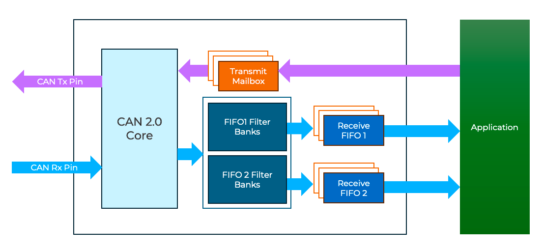
The STM32 Blue Pill’s CAN module, called bxCAN (Basic Extended CAN), supports both standard identifiers (11-bit) and extended identifiers (29-bit), compliant with the CAN 2.0 protocol. The CAN module features two FIFOs (FIFO0 and FIFO1) for receiving messages sent by other CAN nodes. Each FIFO has three stages, meaning it can hold up to three messages in its queue. For transmitting data, the module uses three mailboxes. Messages are sent from the mailboxes either based on their priority or in a FIFO order, depending on the configuration.
Additionally, the module provides 14 filter banks that allow you to select specific packets from the received data. I will explain how to configure these filter banks in the upcoming sections. Below is a simplified block diagram of the CAN peripheral to help you visualize its components.
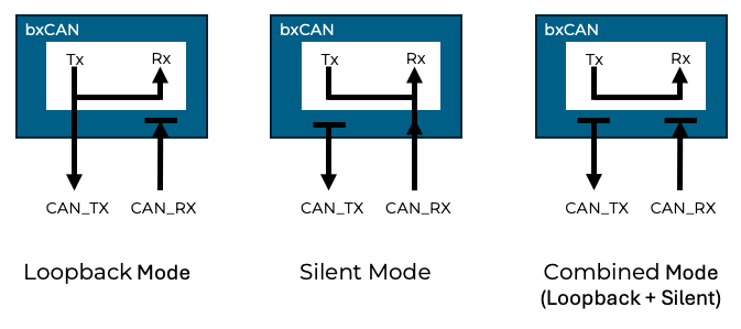
The STM32 bxCAN module supports several test modes, which are useful for different debugging and testing scenarios:
- Loopback Mode: This mode allows you to configure and debug the CAN setup without requiring external hardware. (Explained in detail in this post.)
- Silent Mode: Ideal for observing CAN bus traffic without actively participating or interfering with the communication.
- Combined Loopback and Silent Mode: Enables offline testing without sending signals onto the CAN bus, combining the advantages of loopback and silent modes.
Filter bank configuration
The STM32 Blue Pill’s CAN peripheral includes 14 filter banks, each designed to selectively process CAN messages based on their Identifier (ID). Each filter bank consists of two 32-bit registers: FR1 and FR2. These registers allow you to configure filters in either 32-bit width or 16-bit width mode, with two main filtering options: List Mode and Mask Mode.
Filter Configuration Modes
| Mode | Width | Configuration Details |
| List | 32-bit | FR1 and FR2 are used to configure 2 IDs (1 in each register). |
| 16-bit | FR1 and FR2 are divided into two 16-bit sections, allowing configuration of 4 IDs (2 in each register). | |
| Mask | 32-bit | FR1 configures the ID, while FR2 configures the mask. Bits set to 1 in the mask must match the ID; bits set to 0 are “don’t care.” |
| 16-bit | The first 16 bits of FR1 and FR2 configure the ID and mask for one filter. The remaining 16 bits configure the ID and mask for a second filter. |
This information conveyed in the Figure 230 of RM0008.
Registers used
- CAN Control and Status Register
- Clock configuration registers – RCC_APB1
- CAN Master Control Register – CAN_MCR
- CAN Master Status Register – CAN_MSR
- CAN Transmit Status Register – CAN_TSR
- CAN Bit Timing Register – CAN_BTR
- CAN Interrupt Enable Register – CAN_IER
- CAN Receive FIFO 0 Register – CAN_RF0R
- CAN Filter configuration Registers
- CAN Filter Master Register – CAN_FMR
- CAN Filter Mode Register – CAN_FM1R
- CAN Filter Scale Register – CAN_FS1R
- CAN Filter Activation Register – CAN_FA1R
- CAN Filter FIFO Assignment Register – CAN_FFA1R
- CAN Filter Bank Registers – CAN_FR1 & CAN_FR2
- CAN Mailbox Registers
- CAN TX Identifier Register – CAN_TIxR
- CAN Receive FIFO mailbox Identifier register – CAN_RIxR
- CAN Mailbox Data Length Control and Time stamp Register – CAN_TDTxR
- CAN Receive FIFO Data Length Control and Time stamp Register – CAN_RDTxR
- CAN Mailbox data low/high register – CAN_TDLxR/CAN_TDHxR
- CAN Receive FIFO data low/high register – CAN_RDLxR/CAN_RDHxR
Hands-On
In this hands-on session, we will configure the CAN peripheral in loopback mode to send and receive messages. Follow these steps:
- Task: Send a message (e.g., 2 bytes) with ID 0x102 after configuring the filter with:
- Filter ID:
0x102and Mask:0x7FF
The received message will be printed from the interrupt handler to UART in the followingMsg(id:102, len:2) data[0]:1, data[1]:2 - Filter ID:
- Test Case 1:
- Keep the same filter configuration (
ID 0x102, mask0x7FF). - Send a message with ID 0x103.
The message will not be received in the interrupt handler. This is because the mask0x7FFenforces a strict match with the filter ID, and0x103does not match the configured filter. - Keep the same filter configuration (
- Test Case 2:
- Configure the filter with:
- Filter ID:
0x102 - Mask:
0x7FE
- Filter ID:
- Send messages with ID 0x102 and ID 0x103.
Messages with both ID 0x102 and ID 0x103 will be received. This happens because the least significant bit (LSB) of the mask is0, making the corresponding bit of the message ID a “don’t care” condition. - Configure the filter with:
Steps to be followed
Initialize the CAN peripheral and enable the receive interrupt
Configure the clock control register and interrupts CAN receive interrupts
RCC->APB1ENR |= RCC_APB1ENR_CAN1EN;
prio_grp = NVIC_GetPriorityGrouping();
NVIC_SetPriority(USB_LP_CAN1_RX0_IRQn, NVIC_EncodePriority(prio_grp, 0, 0));
NVIC_EnableIRQ(USB_LP_CAN1_RX0_IRQn);
NVIC_SetPriority(CAN1_RX1_IRQn, NVIC_EncodePriority(prio_grp, 0, 0));
NVIC_EnableIRQ(CAN1_RX1_IRQn);
After powering on the peripheral, we have to set the hardware in to initialization mode by setting the INRQ in the CAN_MCR register and wait until the INAK bit in the MSR is set. This is required to configure the CAN peripheral.
CAN1->MCR |= CAN_MCR_INRQ;
while(0 == (CAN1->MSR & CAN_MSR_INAK));
After initialization, the CAN peripheral will be in sleep mode, exit from sleep mode by clearing SLEEP bit in the CAN_MCR register and wait until SLAK bit in the CAN_MSR is set.
CAN1->MCR &= ~CAN_MCR_SLEEP;
while(0 != (CAN1->MSR & CAN_MSR_SLAK));
Configure the mode as loopback and time quanta(TQ) for TS1 and TS2, I am taking 2TQ for TS1 and 1TQ for TS2 in the CAN_BTR register
CAN1->BTR |= (uint32_t) (CAN_BTR_LBKM | CAN_BTR_TS1_0);Configure filter to receive data
We need to put the filter into initialization mode before configuring in the CAN_FMR register
CAN1->FMR |= CAN_FMR_FINIT;To configure a filter bank, first we need to deactivate it by clearing the corresponding bit in the CAN_FA1R. Please note that this register can only be configured if FINIT bit is set in the CAN_FMR register. (say SEL_FILTER_BANK = 0)
CAN1->FA1R &= ~(1 << SEL_FILTER_BANK);I am using the filter register in 32-bit width. Please not that we are using the standard identifier which require only 16-bit width. But for simplicity I am using not using 16-bit
CAN1->FS1R |= (1 << SEL_FILTER_BANK);Configure the message ID and filter mask in FR1 and FR2 respectively in the selected filter bank( in our case we have selected filter bank 0).
CAN1->sFilterRegister[SEL_FILTER_BANK].FR1 = message_id;
CAN1->sFilterRegister[SEL_FILTER_BANK].FR2 = filter_mask;
Configure filter bank as mask mode (use with ID and mask) rather than list mode.
CAN1->FM1R &= ~(1 << SEL_FILTER_BANK);Assign the filter to any one of the FIFO, I am assigning to FIFO0
CAN1->FFA1R &= ~(1 << SEL_FILTER_BANK);Enable the filter bank and leave from the initialization mode
CAN1->FA1R |= (1 << SEL_FILTER_BANK);
CAN1->FMR &= ~CAN_FMR_FINIT;
Handle the receive interrupt
The number of messages in the FIFO will be stored in FMP0 bits of CAN_RF0R register. The type of ID whether it is basic or extended will be set in IDE bit of CAN_RIR of FIFO 0.
if(CAN1->RF0R & CAN_RF0R_FMP0) {
    if(0 == (CAN1->sFIFOMailBox[0].RIR & CAN_RI0R_IDE)) {
        on_std_msg_received();
    }
}
We can parse the ID of received message from CAN_RIR register and the length of data (DLC – Data Length Code) from CAN_RDTR register of FIFO 0.
uint16_t id = (CAN_RI0R_STID & CAN1->sFIFOMailBox[0].RIR) >> CAN_TI0R_STID_Pos;
uint8_t dlc = ((CAN1->sFIFOMailBox[0].RDTR & CAN_RDT0R_DLC) >> CAN_RDT0R_DLC_Pos);
Parse the actual data from CAN_RDLxR and CAN_RDHxR based on the DLC obtained in the previous step.
data[0] = (uint8_t)((CAN_RDL0R_DATA0 & CAN1->sFIFOMailBox[0].RDLR) >> CAN_RDL0R_DATA0_Pos);
data[1] = (uint8_t)((CAN_RDL0R_DATA1 & CAN1->sFIFOMailBox[0].RDLR) >> CAN_RDL0R_DATA1_Pos);
data[2] = (uint8_t)((CAN_RDL0R_DATA2 & CAN1->sFIFOMailBox[0].RDLR) >> CAN_RDL0R_DATA2_Pos);
data[3] = (uint8_t)((CAN_RDL0R_DATA3 & CAN1->sFIFOMailBox[0].RDLR) >> CAN_RDL0R_DATA3_Pos);
data[4] = (uint8_t)((CAN_RDH0R_DATA4 & CAN1->sFIFOMailBox[0].RDHR) >> CAN_RDH0R_DATA4_Pos);
data[5] = (uint8_t)((CAN_RDH0R_DATA5 & CAN1->sFIFOMailBox[0].RDHR) >> CAN_RDH0R_DATA5_Pos);
data[6] = (uint8_t)((CAN_RDH0R_DATA6 & CAN1->sFIFOMailBox[0].RDHR) >> CAN_RDH0R_DATA6_Pos);
data[7] = (uint8_t)((CAN_RDH0R_DATA7 & CAN1->sFIFOMailBox[0].RDHR) >> CAN_RDH0R_DATA7_Pos);
Finally release the FIFO0, this will decrement the number of pending messages in the FMP0
CAN1->RF0R |= CAN_RF0R_RFOM0;Start CAN peripheral
We have configured everything, now just start the CAN peripheral and exiting from the initialization mode and wait until the hardware acknowledge it.
CAN1->MCR &= ~CAN_MCR_INRQ;
while(0 != (CAN1->MSR & CAN_MSR_INAK));
Enable the interrupt
CAN1->IER |= CAN_IER_FMPIE0;Send the data
CAN send message is straight forward, check if any mailboxes are available from CAN_TSR register and get it from the same register
if(0 != (CAN1->TSR & (CAN_TSR_TME0 | CAN_TSR_TME1 | CAN_TSR_TME2))) {
    tx_mailbox = (CAN1->TSR & CAN_TSR_CODE) >> CAN_TSR_CODE_Pos;
Set standard ID in CAN_TIxR register, length in CAN_TDTR register and actual data in CAN_TDLxR or TDHxR
CAN1->sTxMailBox[tx_mailbox].TIR = (std_id << CAN_TI0R_STID_Pos);
CAN1->sTxMailBox[tx_mailbox].TDTR = len;
CAN1->sTxMailBox[tx_mailbox].TDLR = ((data[1] << CAN_TDL0R_DATA1_Pos) | (data[0] << CAN_TDL0R_DATA0_Pos));
Request the hardware to transmit the data
CAN1->sTxMailBox[tx_mailbox].TIR |= CAN_TI0R_TXRQ;Solution
The complete source code of the solution is available in my git repository, feel free to comment below if you need any additional support.