In this third part of our series, we delve into the heart of the STM32 USB implementation by exploring its USB peripheral. We’ll discuss its components, how they work together, and the steps to configure it as a custom HID device using the STM32 Blue Pill, with a Raspberry Pi serving as the host. By the end of this post, you’ll have a clear understanding of how to configure endpoints, manage the Packet Memory Area (PMA), and respond to host requests.
Overview of the STM32 USB Peripheral
The USB peripheral in STM32 microcontrollers like the Blue Pill is versatile and compact. Key components include:
- Common Registers: Control the overall operation of the USB peripheral.
- Endpoint Registers: Manage individual endpoints for data transmission and reception.
- Packet Memory Area (PMA): A shared memory region used for USB data.
- Buffer Descriptor Table (BDT): Maps endpoints to the Packet Memory Area (PMA).
Each of these components plays a crucial role in USB communication, and understanding their interactions is vital for successful implementation.
Common Registers
The common registers control the global state of the USB peripheral. Key registers include:
- USB Control Register (
USB_CNTR): Enables or disables the USB functionality and handles low-power mode. - Interrupt Status Register (
USB_ISTR): Indicates various USB events like reset, suspend, or endpoint-related interrupts.
Endpoint Registers
Endpoints are communication channels between the USB host and device. The Blue Pill supports up to 8 bidirectional endpoints. Each endpoint has:
- Endpoint Address Register (
EPnR): Configures endpoint type (control, bulk, interrupt), status, and data toggle bits. (n = 0..7)
Packet Memory Area (PMA)
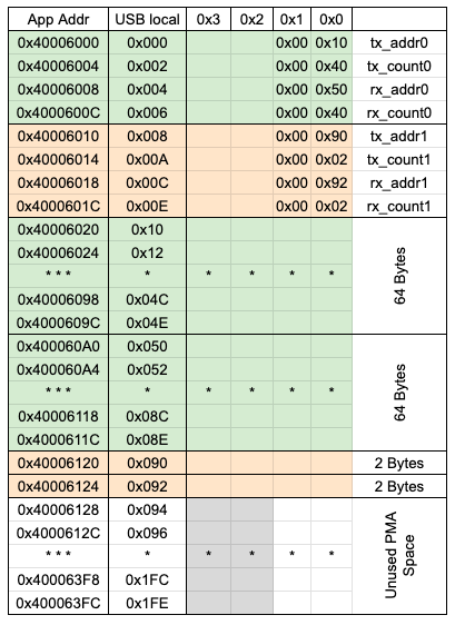
The PMA is a shared RAM used to store USB data packets. The Blue Pill allocates 512 bytes of PMA, shared dynamically among endpoints. The PMA will split into multiple buffers whose address will be kept for each end points in the buffer description table. The PMA starting from the address 0x40006000. All registers in the PMA are 16-bit wide but the addresses are 32-bit aligned. This is done by adding 2 byte unused space in the each registers.
Buffer Descriptor Table (BDT)
The BDT maps endpoint registers to PMA buffers. Each endpoint requires:
- A TX buffer descriptor for sending data to the host.
- An RX buffer descriptor for receiving data from the host.
The BDT entries specify the start address of the PMA buffer and its size. In other words, the Buffer Descriptor Table (BDT), located within the Packet Memory Area (PMA), holds the addresses of the USB transmit and receive buffers. The offset address of BDT from the PMA base should be stored in USB_BTABLE.
The BDT should keep the transmit and receive buffer address in terms of offset from PMA base address as 16-bit address starting from 0x00 is called USB local address. The data can be read/write using the actual 32 bit address starting from 0x40006000 called application address.
Here is the pictorial representation of PMA when 2 endpoints are configured.
USB BUS Connection
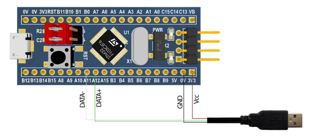
We can connect the blue pill with host in two ways. If you have USB to mini-USB cable you can directly connect with blue pill USB connector. If you have any USB cable with male connector, you strip the other end and connect to the blue pill pin as shown in the image below.
Configure USB peripheral
In order configure the USB peripheral of STM32 bluepill the following steps have to be followed
1. Get PMA address
We have to take the location of PMA into a variable. For this we have two options
- Create a pointer with address 0x40006000.
- Using linker (.ld) script.
The first method is very simple. But using linker script is more standard way. Because it is a way to centralize the memory management and also the compiler and linker can optimize access to the PMA when its location is defined in the linker script, potentially improving performance and reducing instruction overhead.
In the STM32F103C6Tx_FLASH.ld script, add the PMA as third entry of MEMORY object
/* Specify the memory areas */
MEMORY
{
  RAM (xrw)  : ORIGIN = 0x20000000, LENGTH = 10K
  FLASH (rx) : ORIGIN = 0x8000000, LENGTH = 32K
  PMA (W)    : ORIGIN = 0x40006000, LENGTH = 512 /* 256 x 16bit */
}
Add the following code inside SECTIONS. This section helps any variable with attribute .pma to use the PMA,
  /* USB/CAN Packet Memory Area (PMA) */
  .pma :
  {
    _pma_start = .; /* Start of PMA in real memory space */
    . = ALIGN(2);
    *(.pma)         /* Any variable defined the section .pma should add*/
    . = ALIGN(2);
    _pma_end = .;   /* End of PMA in PMA space */
  } > PMA
2. Configure BDT
We already have defined a section in the linker script called .pma. In order to allocate the BDT inside the PMA, we can use the following attribute for the BDT variable.
#define PMA_BDT_ATTR __attribute__((section(".pma,\"aw\",%nobits//"), used))Each entry in the BDT must include the transmit buffer address, transmit byte count, receive buffer address, and receive byte count, each occupying 2 bytes. However, since these fields are stored in memory with a 4-byte alignment, leaving 2 bytes unused, we will define each field as a 32-bit integer. Thus, a BDT entry will be structured as follows:
typedef uint32_t PMAWord_t;

typedef struct {
    PMAWord_t tx_addrs;
    PMAWord_t tx_count;
    PMAWord_t rx_addrs;
    PMAWord_t rx_count;
} usb_buff_desc_t;
Now, define the BDT with required number of endpoints. The 0th endpoint should be used as control endpoint which is used for enumeration requests and responses. We need a second endpoint to send and receive data.
static usb_buff_desc_t PMA_BDT_ATTR buff_desc_table[2];3. Configure the clock
The STM32 blue pill support USB Full Speed (FS) which require at least 48MHz for proper working. Here I am configuring the maximum supported clock in the STM32. For this I am using the external 8MHz crystal with PLL multiplier 9. Here is the function I have used to setup 72 MHz clock. Use the RM0008 reference manual for more details
void config_sys_clock() {
    // Enable the HSE
    RCC->CR |= RCC_CR_HSEON;
    while ((RCC->CR & RCC_CR_HSERDY) == 0);

    // Set flash latency
    FLASH->ACR |= FLASH_ACR_LATENCY_2;

    // Disable the PLL
    RCC->CR &= ~RCC_CR_PLLON;
    while(RCC->CR & RCC_CR_PLLRDY);

    // Configure the PLL
    RCC->CFGR &= ~RCC_CFGR_PLLMULL;
    RCC->CFGR |= RCC_CFGR_PLLMULL9;
    RCC->CFGR |= RCC_CFGR_PLLSRC;

    // Re-enable the PLL
    RCC->CR |= RCC_CR_PLLON;
    while(!(RCC->CR & RCC_CR_PLLRDY));

    // Set the PLL as system clock source
    RCC->CFGR &= ~RCC_CFGR_SW;
    RCC->CFGR |= RCC_CFGR_SW_PLL;
    while(0 == (RCC->CFGR & RCC_CFGR_SWS_PLL));

    // Configure AHB and APB prescaler
    RCC->CFGR |= RCC_CFGR_HPRE_DIV1;            // AHB prescaler
    RCC->CFGR |= RCC_CFGR_PPRE1_DIV2;           // APB1 prescaler
    RCC->CFGR |= RCC_CFGR_PPRE2_DIV1;           // APB2 prescaler

    // Update the global variables with new clock source
    SystemCoreClockUpdate();
}
4. Enable the USB peripheral clock and interrupt:
We have to enable the clock in the RCC register and enable the interrupt in the NVIC
    // Enable USB Clock
    RCC->APB1ENR |= RCC_APB1ENR_USBEN;

    // Enable the interrupt
    uint32_t usb_priority_grp = NVIC_GetPriorityGrouping();
    NVIC_SetPriority(USB_LP_CAN1_RX0_IRQn, NVIC_EncodePriority(usb_priority_grp, 0, 0));
    NVIC_EnableIRQ(USB_LP_CAN1_RX0_IRQn);
5. Reset USB peripheral
The FRES bit in the USB_CNTR register can be used to do a reset as it do by the USB host. The software need to clear this bit in order to exit from the reset state. Configure the address of BDT in the USB_BTABLE register.
    USB->CNTR = (uint16_t)USB_CNTR_FRES;
    USB->CNTR = 0U;
    USB->BTABLE = BTABLE_ADDRESS;              // BTABLE_ADDRESS is 0
6. Enable the Reset interrupt
At the end of USB initialization, we are enabling the reset interrupt. We postponed this to the end to ensure that there is no interrupt has been triggered before the initialization is completed.
    USB->ISTR = 0U;
    USB->CNTR = (uint16_t)(USB_CNTR_RESETM);
Once steps 3 to 6 are completed, plugging the USB into the host will trigger the reset interrupt, invoking the USB_LP_CAN1_RX0_IRQHandler as the RESET flag is set in the USB_ISTR register.
7. Handle the reset event
When the reset even is triggered, we have to perform the following operations
- Clear the BDT data
- Configure control endpoint (EP – 0)
- De-configure the data endpoint (EP – 1), this ensure that any previous data in these registers are reverted back if any
- Enable the USB device.
- Enable the remaining interrupts.
In the following code the pma_ptr will keep the address of next PMA location which is not allocated.
static void usb_reset(void) {
    memset(buff_desc_table, 0, sizeof(buff_desc_table));
    pma_ptr = &_pma_end;

    // Open control endpoint
    configure_endpoint(0, EP_TYPE_CTRL, 0, 0);  // For TX endpoint
    configure_endpoint(0, EP_TYPE_CTRL, 0, 1);  // For RX endpoint

    // Close custom endpoint
    deconfigure_endpoint(1, 0);                 // For TX endpoint
    deconfigure_endpoint(1, 1);                 // For RX endpoint

    USB->DADDR = (uint16_t)USB_DADDR_EF;

    USB->CNTR = (uint16_t)(USB_CNTR_CTRM  | USB_CNTR_WKUPM |
                           USB_CNTR_SUSPM | USB_CNTR_ERRM |
                           USB_CNTR_SOFM | USB_CNTR_ESOFM);
}
8. Configure Control Endpoint and de-configure data endpoint
Configuring the endpoint register is most important step. The important thing is unlike the registers we have used so far, the Endpoint Registers have toggle bits which will toggle its value when we write 1 and remain in the same state if we write 0. Also, this register has read/clear bits. These bits can be cleared by writing 0. But writing 1 doesn’t have any effect. so we should be very careful while configuring these registers.
This step includes
- Configure the endpoint type (Control for endpoint 0 and interrupt for endpoint 1)
- Set endpoint address as 0 for control endpoint and 1 for data endpoint
- Configure the transmit and receive buffer addresses and lengths in the Buffer Descriptor Table (BDT).
- Configure receive endpoint (OUT) status as RX_VALID to accept incoming data
- Configure the transmit endpoint (IN) status as TX_NAK and the length of the transmit buffer to 0 to ensure no data is sent before writing data into the buffer..
static void configure_endpoint(uint8_t endpoint, EPType_t type, uint8_t ep_addr, uint8_t is_rx) {
    uint16_t num_block;
    uint16_t pkt_size = (endpoint == 0) ? EP0_BUFFER_SIZE : EP1_BUFFER_SIZE;

    // Clear the endpoint type field
    USB_EP_REG(endpoint) &= (~USB_EP_T_FIELD) & USB_EPREG_MASK ;

    // Writing 0 to CTR_TX and CTR_RX will clear those
    // bits but writing 1 doesn't have any effect.
    // So set the value CTR_RX and CTR_TX as one everytime
    // we write the data to EPnR register.
    if(type == EP_TYPE_CTRL) {
        USB_EP_REG(endpoint) |= (uint16_t)(USB_EP_CONTROL | USB_EP_CTR_RX | USB_EP_CTR_TX);
    } else if(type == EP_TYPE_INTR) {
        USB_EP_REG(endpoint) |= (uint16_t)(USB_EP_INTERRUPT | USB_EP_CTR_RX | USB_EP_CTR_TX);
    }

    // Set endpoint address, don't touch CTR_TX and CTR_RX bits
    USB_EP_REG(endpoint) |= (uint16_t)(ep_addr | USB_EP_CTR_TX | USB_EP_CTR_RX);

    if(0 != is_rx) {

        // Set receive buffer address for the endpoint
        if(buff_desc_table[endpoint].rx_addrs == 0) {
            buff_desc_table[endpoint].rx_addrs = PMA_ADDR_FROM_APP(allocate_pma_buffer(pkt_size));
        }

        // Set maximum packet size that the endpoint can hold
        if(pkt_size > 62) {
            // BL_SIZE = 1 so that the counter value
            // become number of block * 64
            num_block = pkt_size / 64;
            buff_desc_table[endpoint].rx_count = ((num_block << 10) | USB_COUNT0_RX_BLSIZE);
        } else {
            num_block = pkt_size / 2;
            buff_desc_table[endpoint].rx_count = (num_block << 10);
        }

        // Clear DTOG_RX bit
        if(0 != (USB_EP_REG(endpoint) & USB_EP_DTOG_RX)) {
            USB_EP_REG(endpoint) |= (uint16_t)(USB_EP_DTOG_RX | USB_EP_CTR_TX | USB_EP_CTR_RX);
        }

        SET_EP_RX_STATUS(endpoint, USB_EP_RX_VALID);
    } else {
        // Set transmit buffer address for the endpoint
        if(buff_desc_table[endpoint].tx_addrs == 0) {
            buff_desc_table[endpoint].tx_addrs = PMA_ADDR_FROM_APP(allocate_pma_buffer(pkt_size));
        }

        buff_desc_table[endpoint].tx_count = 0;

        // Clear DTOG_TX bit
        if(0 != (USB_EP_REG(endpoint) & USB_EP_DTOG_TX)) {
            USB_EP_REG(endpoint) |= (uint16_t)(USB_EP_DTOG_TX | USB_EP_CTR_TX | USB_EP_CTR_RX);
        }

        SET_EP_RX_STATUS(endpoint, USB_EP_TX_NAK);
    }
}
To de-configure the endpoint 1, just set its TX and RX status as disabled.
static void deconfigure_endpoint(uint8_t endpoint, uint8_t is_rx) {
    if(0 != is_rx) {
        // Clear DTOG_RX bit
        if(0 != (USB_EP_REG(endpoint) & USB_EP_DTOG_RX)) {
            USB_EP_REG(endpoint) |= (uint16_t)(USB_EP_DTOG_RX | USB_EP_CTR_TX | USB_EP_CTR_RX);
        }

        // Set STAT_RX as disabled
        uint16_t stat_rx = USB_EP_REG(endpoint) & USB_EPRX_STAT;
        USB_EP_REG(endpoint) |= (stat_rx | USB_EP_CTR_RX | USB_EP_CTR_TX);
    } else {
        // Clear DTOG_TX bit
        if(0 != (USB_EP_REG(endpoint) & USB_EP_DTOG_TX)) {
            USB_EP_REG(endpoint) |= (uint16_t)(USB_EP_DTOG_TX | USB_EP_CTR_TX | USB_EP_CTR_RX);
        }

        // Set STAT_TX as disabled
        uint16_t stat_tx = USB_EP_REG(endpoint) & USB_EPTX_STAT;
        USB_EP_REG(endpoint) |= (stat_tx | USB_EP_CTR_RX | USB_EP_CTR_TX);
    }
}
9. Device enumeration
Once the reset is properly handled, the device has to wait to get first request (Device Descriptor request) in the USB enumeration. When any packet received from the host or any packet is ready to sent from the device, the CTR flag in the USB_ISTR register will be set. Also the endpoint number from which the data received will be set in the LSB of the USB_ISTR.
Since the endpoint 0 is for control message, every data received in this endpoint will the requests in the USB enumeration and will be processed from process_control_message function in the following code. Since the next request can be arrived before processing the current request we will process all the request in a while loop until the CTR flag in the USB_ISTR register is set.
10. Process the control messages
If the DIR flag in the USB_ISTR register is 0, it means the transaction is IN (the device will send the data to the host) otherwise the transaction is OUT.
If the DIR=1, we have to check the packet received the corresponding endpoint is a setup packet or not, this can be done by using the SETUP flag in the USB_EPnR register.
If the request is SETUP, we have to parse the incoming message and send appropriate response if the request is a GET request or simply set the data in the device and wait for the next packet if the request is a SET. For this, we will parse the incoming request, check the request type, request and value etc to understand what the type of request it is. This is done in parse_ctrl_msg. Processing request and sending response, setting internal parameters should be done in a state machine, but for simplicity and since the intention of the blog post is to understand the working, I am simply using the switch case method.
Once all requests are processed correctly and sent the requested data to the host, the enumeration stage will be completed and the string descriptors that we have sent during the enumeration will be displayed in the syslog of the host (Raspberry Pi). If you are getting something as the following without any error, Congratulations you have created a custom HID USB device.
[  123.456789] usb 1-1.2: new low-speed USB device number 5 using xhci_hcd
[  123.567890] usb 1-1.2: New USB device found, idVendor=1155, idProduct=22362, bcdDevice=2.00
[  123.567905] usb 1-1.2: New USB device strings: Mfr=1, Product=2, SerialNumber=3
[  123.567912] usb 1-1.2: Product: STM32 Learning Interface
[  123.567917] usb 1-1.2: Manufacturer: STMicroelectronics
[  123.567922] usb 1-1.2: SerialNumber: 887A32C29AA9
11. Sending and Receiving Data
Sending and receiving the data through endpoint is self explanatory, you can go through the code and try to understand because nothing complex there if you are able to understand the enumeration. Here is the complete register level source code for blue pill to use as a Custom HID device. https://github.com/mshafeeqkn/STM32F1XX_Sample_Project/tree/usb_driver